What Is A Plr Function Block Diagram Phase Locked Loop Opera
Pll phase loop locked analog fundamentals basic figure configuration Pll-based block diagram. Xr2212 pll fm demodulator circuit |free electronic circuit diagrams
Block diagram of the PLL used for study. | Download Scientific Diagram
2: complete block diagram of pll control scheme [30]. Block diagram of plc Phase locked loop operating principle and applications
Pll fractional diagram talks cs diorio washington homes
What are user defined function blocks in plc?Plr reaction system based on reference [16] Pll representationBlock diagram of plc system.
Pll practicalThe framework of plr-based model Intro to function block diagramPll complete.
.PNG)
Plc fbd block diagram functional language programming automation industrial
Block diagram of pll.Illustration of the different plr parameters in the plr plot. the upper Block diagram of pll in practicalLenguaje de diagrama de bloques de funciones fbd.
Fractional pll block diagramPll block diagram Logix plc programming fbd language intro confident continuing becoming towardBlock diagram of a basic pll..
![2: Complete block diagram of PLL control scheme [30]. | Download](https://i2.wp.com/www.researchgate.net/profile/Md_Amin8/publication/324173825/figure/fig3/AS:611395095760902@1522779358398/Complete-block-diagram-of-PLL-control-scheme-30.png)
Simplified block diagram of pll implementation in synchronous reference
Function block diagramsBlock diagram of the proposed pll (a) structure, (b) linearised control Pll general block diagram: block level structure representationStep function block diagram complete wiring schemas.
Block diagram of a pll.Solved ques 3 draw the basic block diagram of pll. describe Phase-locked loop (pll) fundamentalsPlr instrument block diagram..

Block diagram of pll system in analyzing transient response
Block function logic ladder diagrams between differenceBlock diagram of the pll used for study. Pll block diagram analog file commons wikimediaBlock diagram of pll on the level of phase relations.
Industrial automation : plc programming languageWhat is the difference between ladder logic and function block diagrams Analyzing pll transient response lockedFile:analog pll (block diagram).png.

Plc automation
Pll block diagram diorio cs talks washington homesDemodulator pll ic circuits working File:all degital pll (block diagram-2).pngPll block diagram degital arduino file digital commons wikimedia code implement basic description.
Pll diagram block principle phase loop locked workingIntroduction to function block programming in rslogix 5000 .


Introduction to Function Block Programming in RSLogix 5000

Phase-Locked Loop (PLL) Fundamentals | Analog Devices
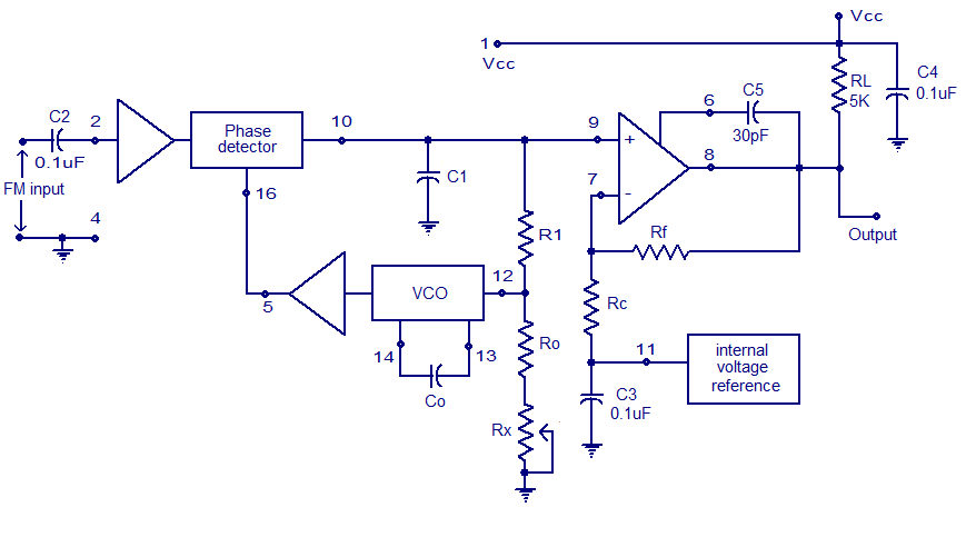
XR2212 PLL FM demodulator Circuit |Free electronic circuit diagrams

Simplified block diagram of PLL implementation in synchronous reference

Block diagram of the PLL used for study. | Download Scientific Diagram

Block diagram of a PLL. | Download Scientific Diagram

Block diagram of PLL. | Download Scientific Diagram